Primary and reduction gyratory crushers
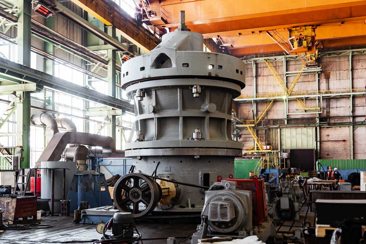
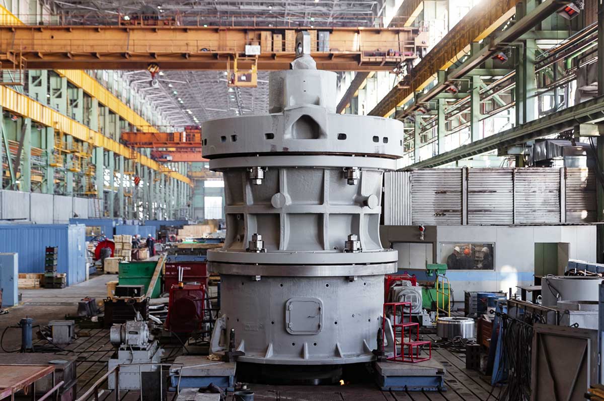


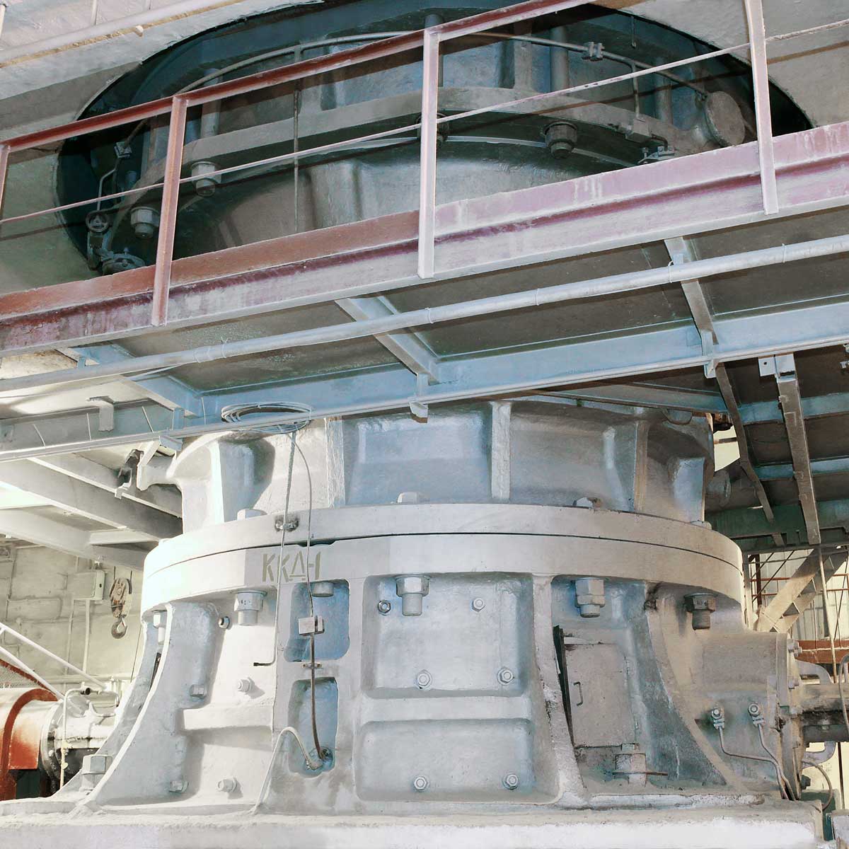
Primary gyratory crushers (KKD) are designed for the primary crushing of ore and rock products at the first crushing stage.
Reduction gyratory crushers (KRD) are designed for the use at the second crushing stage in 4-stage crushing circuits. Due to their high product reduction ratio these crushers allow more efficient use of secondary and tertiary crushers.
Uralmashplant offers a wide model range of primary and reduction crushers with output ranging from 250 to 4200 cubic meters per hour depending on the type and application of equipment and the needs of the customer's process.
Uralmashplant also offers special modifications of these crushers customized to suit the specific process needs of customers, including crusher modifications for the installation on movable platforms in pits and modifications for crushing extra-hard and strong materials and materials with low surface friction coefficient.
| Specifications | KKD-1500/200 (230)М-2P | KKD-1500/200 (180)М-2P | KKD-1500/30 | KKD-1500/180 | KKD-1500/180-2 | KKD-1200/150 | KKD-1200/150-2 | KKD-500/75 | KRD-700/100 | KRD-700/75 | KRD-900/100 |
|---|---|---|---|---|---|---|---|---|---|---|---|
| Width of feed opening, mm | 1600 | 1600 | 1500 | 1500 | 1500 | 1200 | 1200 | 500 | 700 | 700 | 900 |
| Nominal width of discharge opening, mm | 200 | 180 | 230 | 180 | 180 | 150 | 150 | 75 | 100 | 75 | 100 |
| Maximum lump size (5% remainder of oversize material on square mesh), mm, max | 1300 | 1300 | 1200 | 1200 | 1200 | 1000 | 1000 | 400 | 550 | 550 | 750 |
| Throughput with nominal width of discharge opening, m3/h, min* | 3200 | 3000 | 2620 | 2470 | 2470 | 1600 | 1600 | 250 | 880 | 480 | 780 |
| Main drive power, kW, max | 2 х 500 | 2 х 500 | 2 х 400 | 400 | 2 х 400 | 500 | 2 х 200 | 110 | 400 | 250 | 400 |
| Product size factor, max | 1,7 | 1,7 | 1,7 | 1,7 | 1,7 | 1,7 | 1,7 | 1,7 | 2,0 | 2,0 | 2,0 |
Product size factor, mm, max: - length - width - height | - 13 030 9 040 10 250 | - 13 030 9 040 10 250 | 18 080 7 180 10 105 | 12 450 7 340 9 975 | 19 100 7 340 9 975 | 10 320 7 170 8 380 | 16 010 7 170 8 380 | 4 500 4 335 4 340 | 11 505 6 950 8 320 | 8 250 5 970 7 590 | 10 885 6 885 8 780 |
| Crusher weight (without spare parts), t, max | 500 | 500 | 473 | 429 | 450 | 290 | 305 | 45 | 262 | 157 | 273 |
The throughput values indicated above are given for material with compression strength of 100 to 150 MPa and minimal content of clay, moisture, and fines in feed.
The throughput of crushers can vary over a wide range depending on the physical and mechanical properties of material and particle size distribution in feed.
Supply of main drive motors with power different from the table above is possible on the customer's request in consultation with our specialists.
Design features:
- Mainshaft with a hydraulic support (hydraulic setting adjustment) and an automatic mainshaft height adjustment function.
- Heavy-duty (rated for any severe operating conditions) main assemblies of the crusher: the bottom shell, the top shell, the spider, and the main shaft.
- V-belt drive with a phase-wound rotor motor and soft starting.
- Automatic grease lubrication of the top suspension bushing, dust seal, and drive bearings.
- Circulating oil lubrication of the eccentric and gearing.
- Automated control system.
- Hydraulic system for the tightening of bolted joints between the top shell and the spider (hydraulic jacks).
- Remote measurement of the discharge opening size.
- Idle operation without any limits.
Design

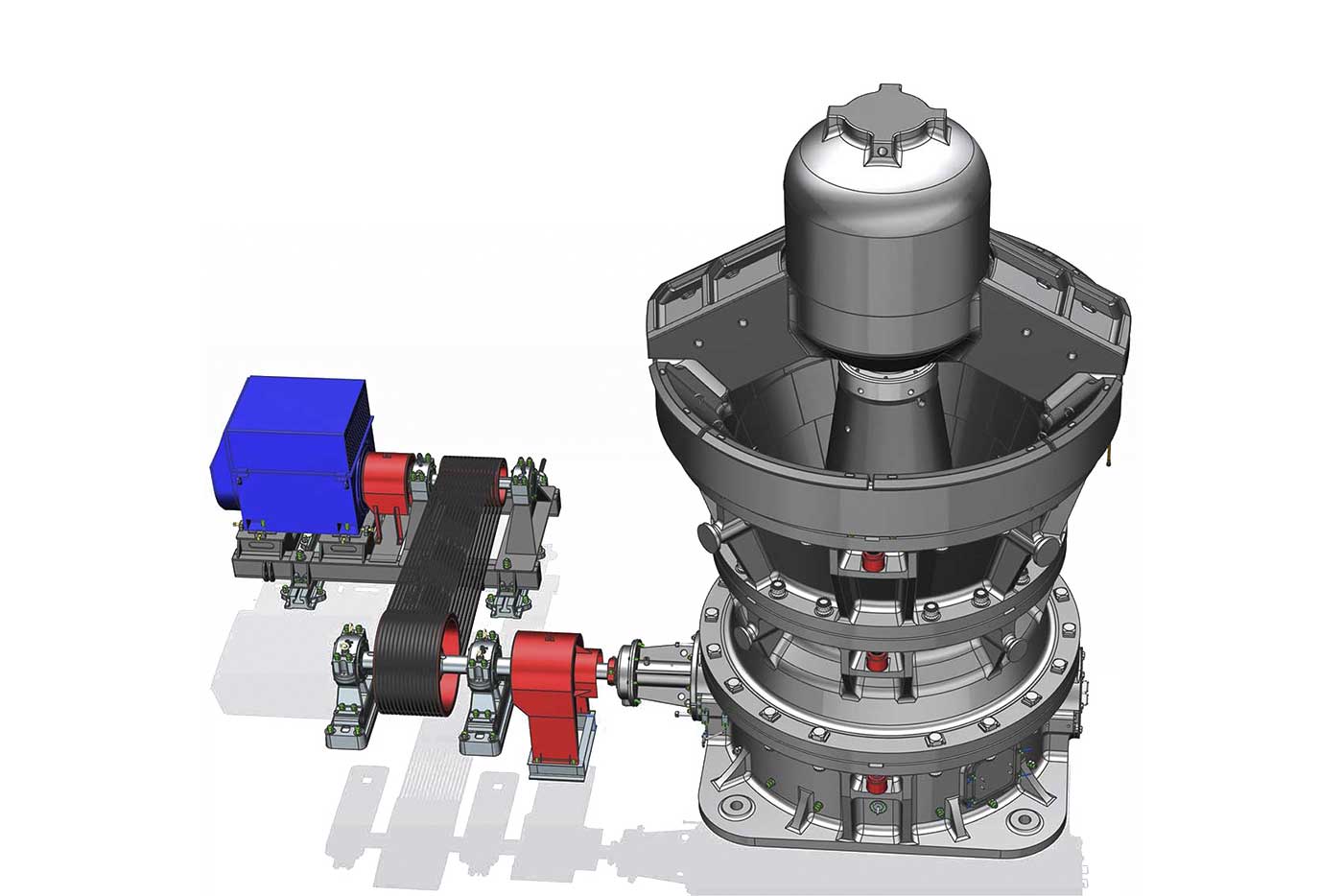


The design team of Uralmashplant uses individual approach to customers. Before commencing design development works, we study process conditions at the customer's site where UZTM-brand equipment is going to be installed. After that we analyze a lot of factors, such as where and how the crusher will be installed, what are the customer's needs, etc. The terms of reference are developed based on this information and then the customer's desires and requirements are implemented in the design and optimal delivery conditions are determined.
The designers of Uralmashplant employ high-accuracy analytical methods and tools. Our designers of primary and reduction crushers use modern design systems such as Siemens NX, ANSYS engineering software complex, ROCKY software complex, and new analytic servers. 1D functional modelling system is used for the simulation of complex processes in mechanical, hydraulic, and pneumatic systems to define and chose optimal system parameters at the modelling stage of design process.
3D models (digital copies of machines) are used for the assemblability analysis of crushers. These models are also used in the development of documents for the installation of a crusher at site.
In this manner, we can analyze different layouts of equipment, locations of maintenance and repair areas, and routing of material feed lines, cables, and pipelines. In addition, the use of the digital copy of a machine significantly facilitates the development of assembly and dismantling schemes.
The rated service life of primary and reduction crushers made by Uralmashplant is at least 15 years, and the actual service life of our crushers is more than 20 years.
Production
Our primary and reduction crushers are designed and manufactured at the facilities of Uralmashplant JSC (Ekaterinburg). Steel castings for our equipment are supplied by the foundry branch of the UZTM-KARTEX Group located in Kolpino, St.-Petersburg. Subassemblies and components for the KKD and KRD crushers of Uralmashplant have high reliability and are procured from leading manufacturers.
We conduct quality control at all stages of the production process in accordance with design requirements. Quality control inspection types include: ultrasonic testing of welds, magnetic-particle examinations, x-ray examinations, visual examinations, and measurements.


Testing
Full trial assembly and factory testing of crushers in witness of the customer's representatives are conducted on a special patented testing stand that has to equivalents in Russia and CIS countries. This strand is designed for testing of all crusher types (jaw crushers, cone crushers, and gyratory crushers) including the largest model in the range offered by Uralmashplant, KKD-1500/180. The stand can accommodate two crushers at the same time.
15 performance parameters of a crusher are monitored during the factory testing. These parameters include: throughput, mainshaft rotation speed, crushed product size, feed size, material reduction ratio, mainshaft gyration (oscillation) speed, temperature of oil and bearings, pressure in hydraulic and lubrication systems, visualization of PCS parameters, etc.
The stand is equipped with a modern PLC-based information system. The system records the indications of sensors located in different monitoring points on a crusher and on its lubrication system. These data are displayed on the operator's panel and stored in the system memory. A report to be attached to the factory testing certificate is issued automatically after the completion of the test.
The factory testing significantly reduces time and labor costs for the adjustment and commissioning of equipment at site.
Electrical equipment and crusher control system (process control system)
All electrical components are connected by the controller-based automated control system. The controller shall be installed in a crusher control cabinet. The control system monitors the parameters of the main crusher units (bearing temperatures, discharge opening size, etc.) through sensors, generates drive star and stop signals, interacts with the upper level process control system (PCS of a process area or a shop), and connects the crusher into the integrated process control system of a production plant.
All parameters monitored by the PCS are displayed on the screen of the crusher control panel.
Bottom shell and liners
The bottom shell is made of a steel casting. Its heavy flanges and cast inter-peripheral ribs ensure the required rigidity. The shell is protected from wearing with wear-resistant manganese steel liners.
The shell liners are designed to protect the inner surfaces of the shell from rock particles passing through the crusher. The liners include: liners protecting the inner vertical walls of the shell, liners protecting the ribs fixing the central sleeve, guards of countershaft boxes, guards of the mainshaft sealing sleeve, and guards protecting the bottom shell flange for the installation of the discharge setting adjustment cylinder. All shell liners are cast from manganese steel and fixed on the shell in saddles and with bolts.
The top shell, special grooved concaves, the upper and lower rings of the top shell.
The top shell is one of the base parts of the crusher. It consists of the upper and the lower rings forming the shell body and concave liners forming rows 1 to 5. The first row is equipped with reinforced concave liners.
Special grooved concave liners are used in the top row of the mainshaft liner and rows 4 and 5 of the shell. These liners ensure more efficient crushing if crusher feed contains a lot of large lumps (1000-1500 mm fraction) as compared with standard liners. They also reduce the duration of a large lump crushing cycle in the top and middle areas of the crushing chamber. The liners of the first row of the shell are reinforced.
Design innovations implemented in the concave and mantle liners made it possible to:
• reduce the duration of a large lump crushing cycle in the top area of the crushing chamber due to the grooved liners of the shell and mainshaft;
• reinforce the liners of the first row of the shell.
Mainshaft assembly, mainshaft mantles liners
The shaft is made of alloyed steel, heat-treated, and strain-hardened.
Grooved lining in the top area of the mainshaft showed itself to be highly efficient during operational tests.
Hydraulic cylinder of the discharge opening adjustment system (GRSch modifications)
The width of the discharge opening is reduced by lifting the mainshaft (a hydraulic unit pumps oil into the hydraulic cylinder), and increased by lowering the mainshaft (oil is returned to the tank of the hydraulic unit).
Spider
The rim of the spider has who detachable beam segments for the ease of transportation. The central hub of the spider is connected to the rim with two box-section arms. The hub is protected with a steel-cast cap. In some crusher modifications the cap is protected with liners which are interchangeable with middle mantle liners.
The inner surfaces of the top shell assembly, shaft boxes and ribs of the bottom shell, arms and rim of the spider are protected from wearing with wear-resistant manganese steel guards.
Drive and countershaft.
The crusher is driven by a motor through a V-belt transmission. The motor is mounted on a special frame with skids and a screw-type belt tension adjustment mechanism. The crushers can be used with single or dual drives.
The countershaft transmits torque from the drive shaft to the eccentric through the bevel gearing.
Eccentric assembly
The eccentric rests on the bottom shell through a step bearing. The step bearing consists of three rings: the top and the bottom rings are made of steel and the middle ring is made of tin bronze. The outer and the inner surfaces of the eccentric are covered with antifriction babbit coating. Both surfaces have longitudinal cooling oil grooves. Two eccentric design versions are available: with cylindrical mainshaft end portion and with centered loading.
Production and operation statistics
430
Manufactured
42
In operation
KKD crushers are being manufactured since 1936 and KRD crushers since 1956
| Enterprise | Company | Year of commissioning | Model | Country | Q-ty |
|---|---|---|---|---|---|
| Kachkanarskiy GOK | EVRAZ | 2001 | KRD-700/100 | Russia | 1 |
| Pechenganickel | Norilsk nickel | 2001 | KKD-1500/180-2GrSHCH | Russia | 1 |
| Karelskiy okatysh | Severstal | 2002 | KKD-1500/180 | Russia | 1 |
| Coal India – Samanta | Severstal | 2003 | KKD-1500/180GrSHCH | India | 1 |
| Kachkanarskiy GOK | Severstal | 2003 | KRD-700/100 | Russia | 1 |
| Kachkanarskiy GOK | Severstal | 2004 | KRD-700/100 | Russia | 1 |
| Inguleckiy GOK | Metinvest | 2005 | KKD-1500/180 | Ukraine | 1 |
| Mikhaylovskiy GOK | Metalloinvest | 2005 | KKD-1500/200GrSHCH | Russia | 1 |
| Karelskiy okatysh | Severstal | 2006 | KKD-1500/180 | Russia | 1 |
| Norilsk nickel | Norilsk nickel | 2006 | KRD-700/100 | Russia | 1 |
| Severnyi GOK | Metinvest | 2006 | KKD-1500/180 (nodes) | Ukraine | 1 |
| Centralnyi GOK | Metinvest | 2006 | KKD-1500/180 | Ukraine | 1 |
| Yuzhniy GOK | 2007 | KKD-1500/180-NG-2P | Ukraine | 1 | |
| NMDC | 2008 | KKD-1500/180 | India | 1 | |
| Zhezkazgantsvetmet | Kazakhmys | 2009 | KKD-900/160 | Kazakhstan | 1 |
| Lebedinskiy GOK | Metalloinvest | 2009 | KKD-1500/180 GVP | Russia | 1 |
| Sterlitamakskoe PO Soda | Syryevaya companiya | 2010 | KKD-500/75 | Russia | 1 |
| Norilsk nickel | Norilsk nickel | 2011 | KRD-700/100 | Russia | 1 |
| Severnyi GOK | Metinvest | 2011 | KKD-1500/180-NG-2P | Ukraine | 2 |
| SSGPO | ENRC | 2011 | KKD-1500/180 | Kazakhstan | 1 |
| Apatite | FosAgro | 2012 | KKD-1200/150 GVP | Russia | 1 |
| Arсelor Mittal | Arсelor | 2012 | KKD-1500/180 | Ukraine | 1 |
| SSGPO | ERG | 2012 | KKD-1500/180 | Kazakhstan | 1 |
| SSGPO | ERG | 2013 | KKD-1500/180 | Kazakhstan | 1 |
| Apatite | FosAgro | 2013 | KKD-1200/150 | Russia | 1 |
| Syryevaya companiya | 2015 | KKD-500/75 | Russia | 1 | |
| Stoylenskiy GOK | NLMK | 2017 | KKD-1500/180 | Russia | 1 |
| Yuzhuralzoloto | YUGK | 2018 | KKD-1200/150 | Russia | 1 |
| Karel'skiy okatysh | Severstal | 2019 | KKD-1500/180М | Russia | 1 |
| Stoylenskiy GOK | NLMK | 2019 | KKD-1500/180-2P (modernization) | Russia | 1 |
| Stoylenskiy GOK | NLMK | 2019 | KKD-1500/180-2P | Russia | 1 |
| Inguleckiy GOK | Metinvest | 2019 | KKD-900/100 | Ukraine | 1 |
| Karelskiy okatysh | Severstal | 2020 | KKD-1500/180М | Russia | 2 |
| Yuzhniy GOK | Metinvest | 2020 | KRD-900/100 | Ukraine | 1 |
| Inguleckiy GOK | Metinvest | 2021 | KKD-900/100 | Ukraine | 1 |
| Yuzhniy GOK | Metinvest | 2021 | KKD-900/100 | Ukraine | 1 |
Request a quotation
Fill-in the inquiry form and we will send a reply to the e-mail address indicated.